Half Cell Survey Method for Locating
Corrosion in Concrete Structures

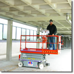
concrete bridge soffit
A half cell survey is an effective method of locating corrosion in concrete structures. Watch this video of a half cell survey >>
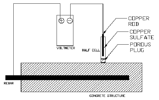
A half cell is a reference electrode. It consists of a sealed plastic tube that is filled with a saturated solution of copper sulfate, through the top of which a copper rod is inserted. The assembly is called a "Copper Half Cell," often abbreviated "CSE."
The bottom of the half cell is a porous ceramic that allows the saturated aqueous solution of copper sulfate to contact the concrete. The copper rod is connected to a negative terminal of a voltmeter. The positive terminal of the voltmeter is connected to an exposed reinforcing steel bar (rebar) and the potential difference is measured by the voltmeter. The readings are expressed in negative volts or negative millivolts (mv) as shown in Table 1 below.

Figure 1: Schematic of setup of a half cell survey
ASTM International has established criteria for rebar corrosion as shown in Table 1. According to the criteria, when the potential difference reading by a half cell over a rebar is more negative than -426 millivolts, severe corrosion is taking place at the rebar that is in the concrete under the half cell.
| Open Circuit Potential (OCP) values | ||
|---|---|---|
| mV vs. SCE | Corrosion Condition | |
| <-426 | <-500 | Severe corrosion |
| <-276 | <-350 | High (>-90% risk of corrosion) |
| -126 to -275 | -350 to -200 | Intermediate corrosion risk |
| >-125 | >-200 | Low (10% risk of corrosion) |
Table 1: ASTM C876 Criteria for Corrosion of rebar in concrete structures
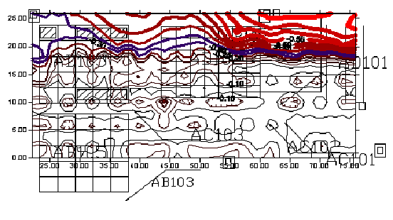
The results of a half cell survey are often displayed as a topographic map as shown in Figure 2. The thick red lines indicate where rebars require cathodic protection. The blue areas indicate locations where intermediate corrosion risk exists. The thin black lines show where rebars do not corrode.

Figure
2: Cutoff of a plan view (bird's eye view) of bridge portions
which require cathodic protection